Tuesday, July 27, 2010

Designing a brush mill

Quite often, I make things that I only end up using a few times. The following is an example.

This post is chronologically out of place. It should have been posted before I considered spray drying. I'm not sure of its future viability in 3D printing, as the particle shape it creates dosen't seem conducive to spreading (see previous posts). Still, a fair bit of engineering and thought went into this project so I thoght it might be of future help. I present it here as food for thought. 

In order to fully mix the ceramic body, it was first wet mixed in slurry form and then completely dried. It was now in lump form. The question was how to get this stuff down to 200 mesh size. I used a combination of jaw crushing and plate milling, but that only got it down to about a 60 mesh. I could have tried sieving the material by hand but the yield would not have been very good (most of the material would not have passed 200 mesh; our plate mill creates -60 mesh material). In its dry state, clay is quite friable. All I really needed was a system that would physically rub the clay against the screen. This rubbing would break down the clay and get it past the screen.

Enter: Hyojin Lee

Hyojin works in the Engineering Department here at AU. He introduced me to a machine he had designed a while back. The machine was designed to mill alumina fibers. It used a rotating rotor with 8 metal rods which rubbed the fibers against a coarse screen (an 8 mesh screen). In doing so, it broke the fibers down, essentially acting as a mill. The beauty of this system was that it was gravity fed, so that there was always material in contact with the screen. Furthermore, the trough which supported the screen was spring-loaded and could travel independently of the rotor. The springs pulled the screen upwards, ensuring contact between it and the rotor blades. This was important so it could adjusted contact as things wore down.

The one issue with using it in my application was that my material and screen were much finer than what the machine was built for. The original rotors were much too coarse and wouldn't have made enough contact with my finer screen and materials. I needed something more pliant.

My solution was to replace the hard metal rotors of the original design with door brushes made of short nylon fiber (courtesy of MSC). These brushes gave me enough rigidity to force the clay against the screen, but enough flexibility that they could better account for irregularities in the geometry of the system. Their softness was also a good thing, given that a 200 mesh screen is fairly thin and wouldn't hold up to constant contact with metal rotor blades for very long.

The following images are a brief overview of the project.


The unmodified unit (left). On the right, the door brush material I bought came in 72" lengths. I cut it down and drilled the holes for it on my CNC mill (right). In fact, all parts were milled prior to assembly (CNCing is perfect for this type of work).


All critical parts were modeled in Rhino prior to starting, so I knew what lengths and what size holes to cut. Toolpaths for everything were created in RhinoCam. In order to ease alignment, I milled out recessed areas on the two end plates for the rotors. This allowed for a slip-fit (left). The image on the right shows all the components before assembly.


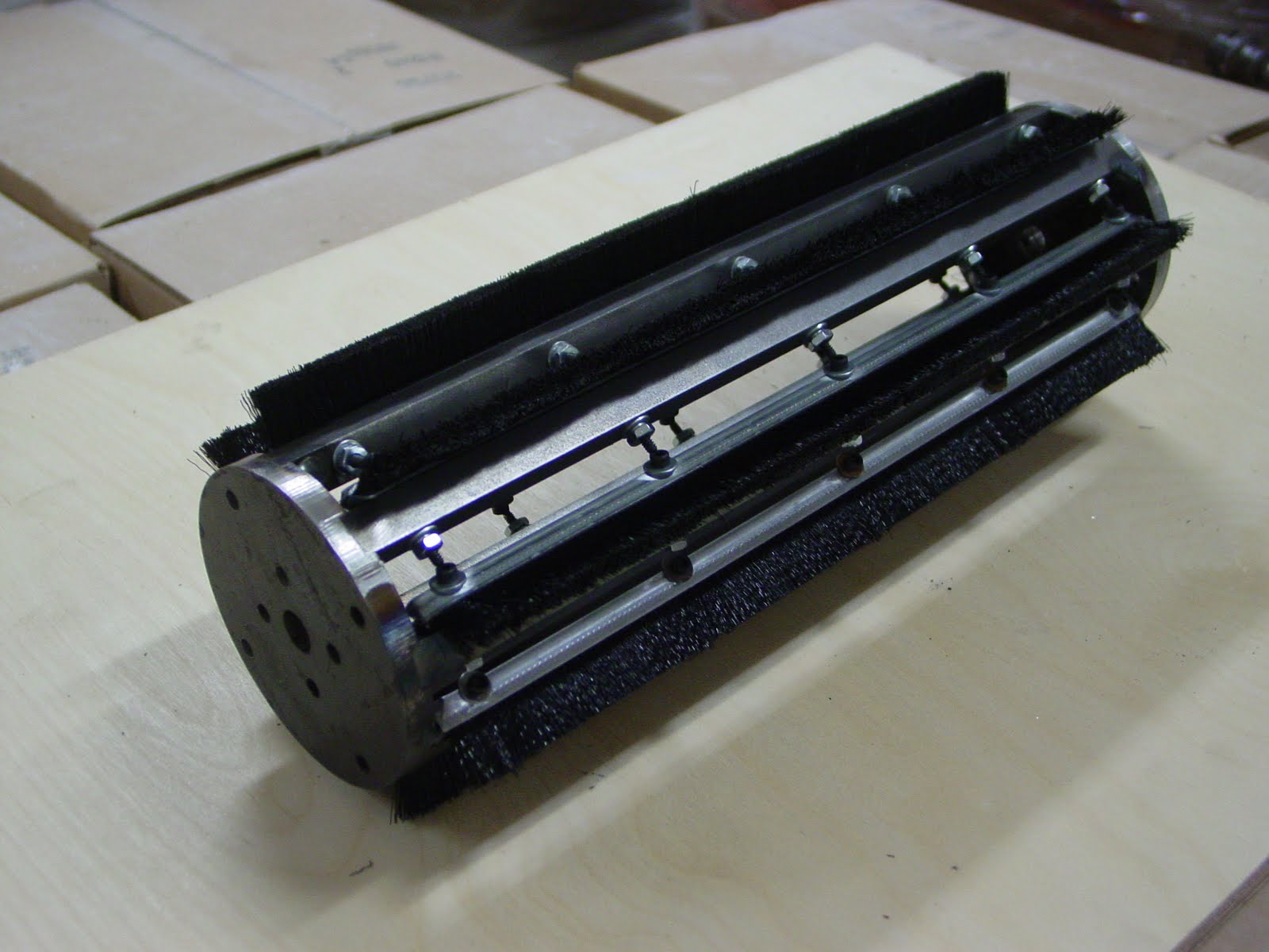
The rotors were welded in place. The brushes were then attached using hex bolts (in case I ever need to replace them).This thing weighs a ton... almost literally.


Detail of brushes and bolts (left). On the right, the original rotor, and its replacement, the newly designed brush-rotor.


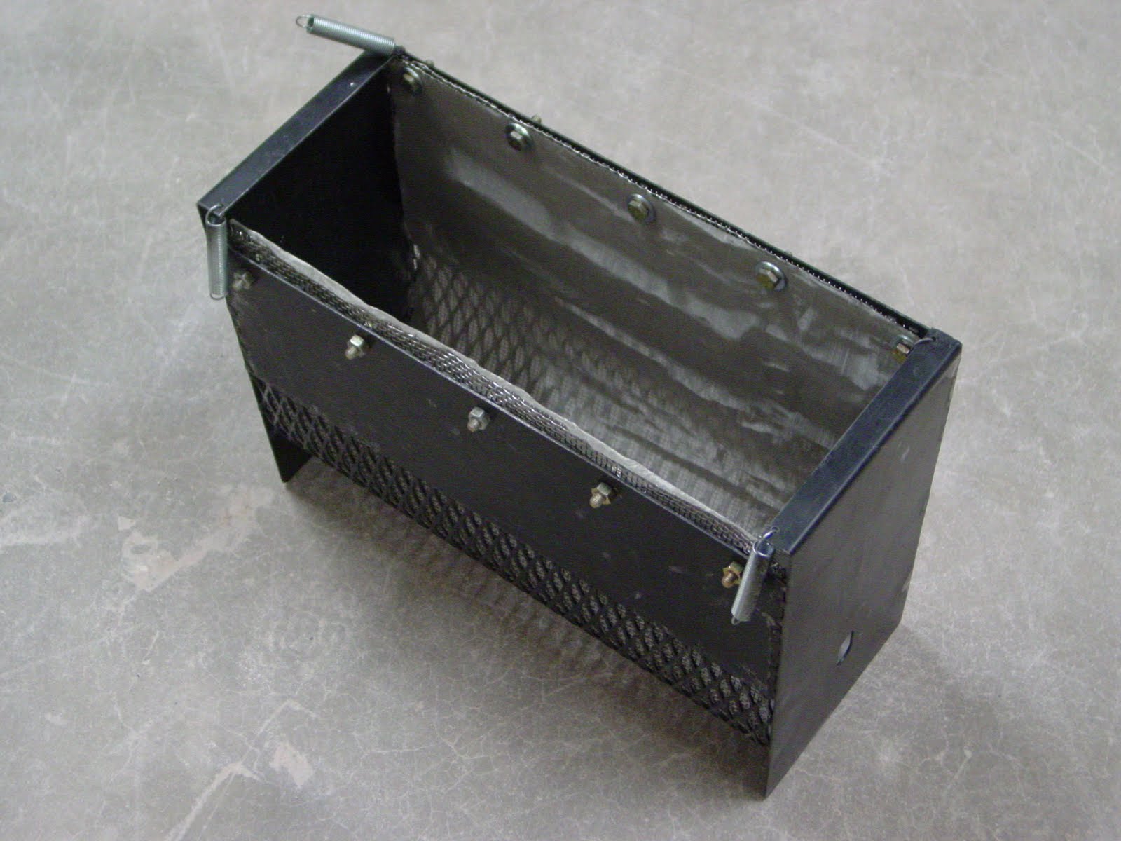
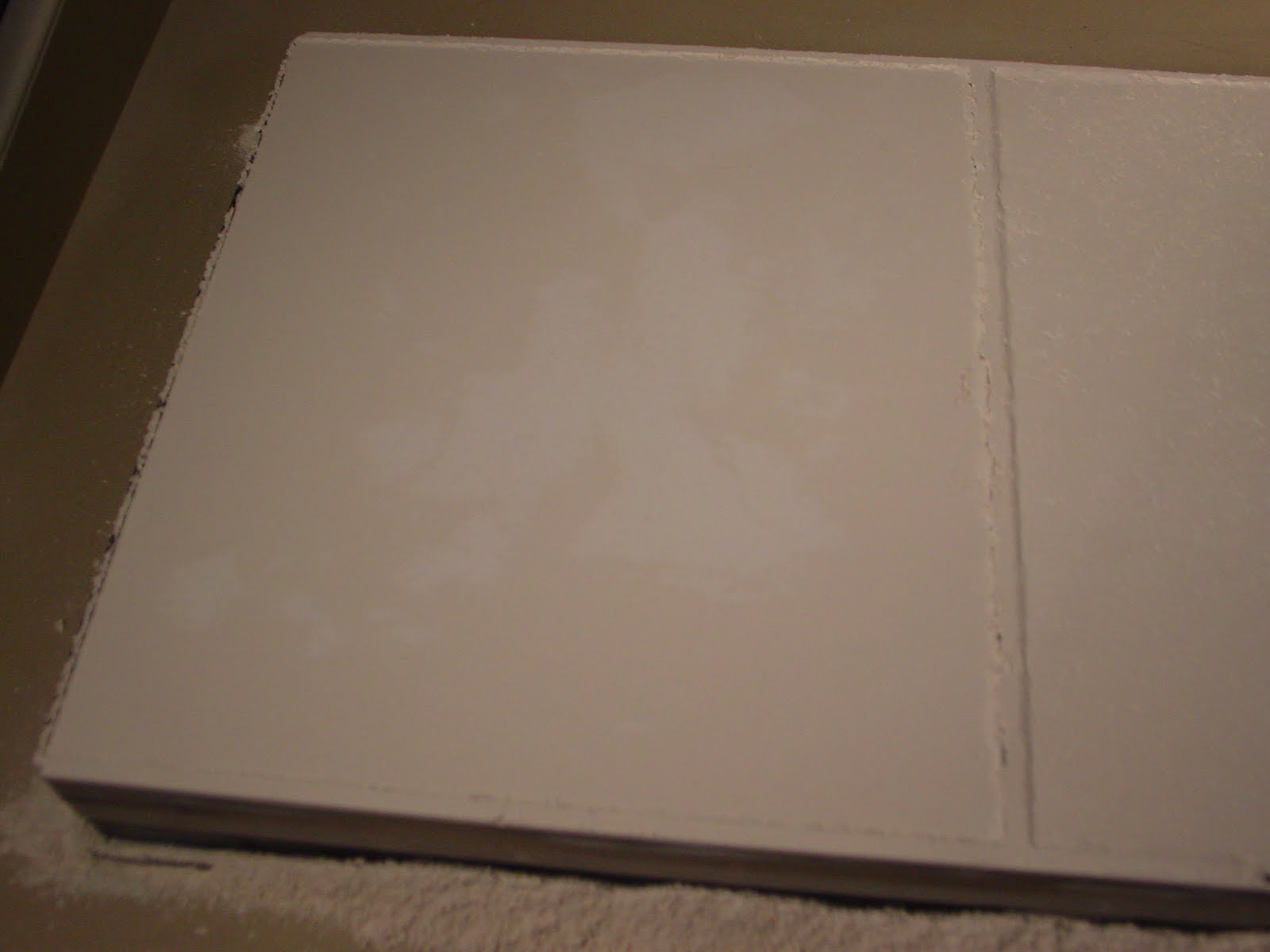
The metal trough has an arc-shaped bottom which is slightly larger than the diameter of the rotor assembly (top left). This ensures good contact between the rotor blades and the screen. In the top right image, a closeup of the screen layers. The finer screen is the 200 mesh count. I decided to back this up with an 8 mesh screen for extra support. Both screens are stainless. The bottom image shows the trough fully assembled. Note the dangling springs. These pull the unit upwards towards the rotor during use.


On the left, a view of the rotor after its been loaded with material. On the right... -200 mesh material collecting below the machine after running it for several minutes.


Here is a video of the whole process in action... http://www.youtube.com/watch?v=3qqzw2xjciM


Thursday, July 8, 2010

Re-designing the dry mixer

These are a few ideas I'm considering for a new dry mixer. These are all based on commercial ribbon mixers. A ribbon mixer uses a helical design to move material throughout its volume. When designed properly, its is a very effective way to mix because virtually all the material is constantly moving. Also, it is possible to design in a way that avoids corners (corners = dead space = stagnant material = no mixing).

I plan to continue using the 5-gallon format as its universally available, inexpensive, easily cleaned and cheap!


The following are a few iterations on a possible design. Arrows in the images represent flow of material...


Version 1. Inner helix moves material in one direction. Outer helix moves material in opposite direction to the smaller inner helix.


Version 2. Similar to version 1 but this is a dual start design: two helixes for both inner and outer sections. This should improve mixing.


Version 3. Helixes are mirror around the middle point of the axis. Outer helixes bring material from the ends of the chamber towards the middle, while inner helixes bring it from the middle outwards. Material converges and diverges at the middle and ends of the container. One drawback to this design is that there are corner areas where material may collect and stagnate. I've highlighted one of the two starts for the outer helix to make this clearer. There are in fact 4 points where this happens (2 for the outer helixes, 2 for the inner helixes).


Version 4. Similar to version 3 but here one side of the helixes has been rotated 90 degrees. This avoids the corners in version 3.


The following video shows a commercial ribbon blender in action... http://www.youtube.com/watch?v=LKeMvSyq_4U. The main difference between commercial units and the one I am designing is that in my design, the blades are fixed relative to the mixing chamber, which simply rotates on a ball mill unit.

I'm leaning towards version 4. I plan to use stainless or aluminum for the central shaft and perhaps Plexiglas for the helixes. I also want to make the entire helix assemble removable from the bucket for easy cleaning.

I met with an engineer today to go over this. His opinion is that while ribbon mixing is a decent approach, it won't be effective with regards to clumped materials (specifically the powdered sugar in the recipe I'm using). To really mix well, we need to consider a high-shearing mixer (for our purposes, shear = friction). We have a Muller mixer which mixes using high shear. The high shear comes from the two solid-steel wheels which rotate around the center of the machine while running over anything in their path. Any lumps of material will be quickly broken up and dispersed. Scrapers reposition material in the path of the wheels, ensuring that everything comes in contact with the wheels. We use a Muller mixer to mix plastic clay bodies on a daily basis. It is truly an awesome machine!


A Muller mixer


Regardless, I will build version 4 above to replace my current dry mixer for general use.

Dry mixer

Here are a few images of the dry mixer I am currently using. This has served me very well over the years for dry mixing larger batches of glaze and other materials for use in ceramic testing.

The container is a 5-gallon bucket. The fins are made of Plexiglas which are held in place with regular angle braces, nuts and bolts. The fin design was inspired by the lowly clothes drying machine. I recently added the wire mesh as way to further promote the breakup of agglomerates.


Dry mixer


After filling with dry powders, the bucket is closed and placed on a ball mill unit where it rotates (I usually leave it running overnight).


Dry mixing bucket on the ball mill unit.


A few issues with this design:

1-There must be an optimal amount of powder. Too much powder and thorough mixing won't happen. I'm not sure what the optimum amount is for this design. I usually don't fill the container more than halfway.

2-As the bucket is slightly sloped, over time material will accumulate on one of the two ends of the container. Movement is happening axially (thanks to the fins) but not across the axis from end to end. This isn't good! Several times during a mixing cycle, I will pick up the bucket and shake it back and forth to redistribute materials. This should really happen continuously through the design of the mixer itself.

3-Pockets. The design has several corners, or pockets where material can get lodged and not flow freely. This is absolutely not good for mixing! I alleviate this by tapping the container several times during the mixing cycle. Again, this should be eliminated in a better design.

Given points 2 and 3 above, I am working on a better design...

Wednesday, July 7, 2010

Printing with spray-dried powder

I just finished an initial test with the spray-dried powder. It’s amazing how much particle shape (a.k.a. particle morhology) affects how particles move. I'm starting to realize that mesh size is only part of the answer. Morphology is just as important, if not more so. These spherical particles move almost like a liquid. They don’t agglomerate (even in these current humid summer conditions).


CDF P-MF #2 on the left; spray dried material on the right. Note the lack of agglomeration with the spray-dried material.


The powder spreads very consistently with no streaking. It also packed very nicely, with no apparent need to compress the feed chamber (it has nowhere to compress to!).


There is nothing dramatic to note here. Both feed and build sides performed perfectly.


Detail of feed and build sides using spray-dried powder.


One thing I did notice… I occasionally found hairs in the powder on the feed side. I think these are due to the brush I am using, as its hairs sometimes find their way through the mesh.

Despite this being only ceramic materials, with no sugar or Maltodextrin, I decided to run a part. There were no issues here either. Unlike in previous cases where powder was not spreading properly, the surface filled predictably after each pass, so the binder was only ever applied to fresh powder.


A couple of images during the print. The image on the right is taken during a layer spread and shows that the spreading is occuring consistently between each layer.


A couple images after the print. There is almost no shrinkage (just a small hairline crack on the surface shown on the right). This compares favorably with the previous tests and suggests that the material is well packed with less potential for shrinkage.


I tried removing the object after printing but the part crumbled under its own weight (so that's why you need a binder!). Adding sugar/Maltodextrin in future tests should give the part post-printed strength. It may also increase shrinkage. For now I’m just excited to have figured out the basic physical requirements for a printable medium!

Next on the agenda: gain access to the spray drier so I can start batching some spray-dried powder from scratch.

Screening spray-dried powder

I just finished screening the spray-dried powder. I opted out of using the 200 mesh as the yield for the powder I have would have been very low and it would have taken an insane amount of time. I don’t know what the largest particles are but much of it doesn’t pass a 6o mesh screen. I settled on using a 100 mesh screen instead. Even at this coarse resolution, I ended up recovering only about 1 liter of powder from about 20 liters of the original material. Of course if this works out, I will have the material sprayed at a much finer size which will yield much higher returns.

I’ve recently built a vibration machine for screening and used this to make the process more bearable. As the screen vibrates, I use a fine brush to move the material around, encouraging the finer stuff to pass through. I’m also mindful not to push too much as this will start to grind the granules which I obviously don’t want. When I was done, the result was quite shocking: the screened spray-dried powder is much denser than comparable powder, and as I was hoping, it doesn’t agglomerate. I can’t see why this won’t work, but I’ve been wrong too many times before to declare victory. We shall see.

Rollin', rollin', rollin'...

It seems that although the discrete particles of the materials I have crushed and screened are less than 200 mesh, they are not rolling as they spread. Rather, they are binding and agglomerating as they are spread across the build area.

I really think that at this point, the issue has to do with morphology of the particle shape. I think that using a spray dried particle may solve this issue, as spray dried material is granular and will “roll” much better.


SEM images of a porcelain body I had spray-dried earlier this year (thanks Gary!).
 

We have a couple of spray driers. One is very high-tech and is used for nano-powder preparation. If I use it, it will require absolute cleaning after use (probably a few hours worth of work) as clay bodies are not normally passed through it and it requires total sterilization for its normal day-to-day use. The other spray drier is better suited to my needs as it is used with clay bodies on a regular basis. Neither of these are options till Tuesday. In the meantime, it would be nice to approximate what I will get. I just happen to have about 100 lbs of spray dried material (sometimes being a pack rat is a good thing!). Not sure what the recipe for it is, though I think it’s probably a bone china recipe from Lennox China. A quick test revealed that some of it passes through a 200 mesh screen. Time for some more screening!


Before I go on, here is a useful chart that gives a picture of relative and absolute sizes:


Second clay recipe: CDF P-MF #2

This second batch is a variatioon on the first, using the same materials passed through a much finer mesh...


CDF P-MF #2
66.6% CDF P-MF Cone 6 Porcelain (-200 mesh)
16.6% Powdered Sugar (-200 mesh)
16.6% Maltodextrin (-200 mesh)


I decided against packing the material tightly into the feed chamber. I simply filled the chamber and lightly compressed the top with the screen plate.
First I tried using 0.008” layers. This seemed too large a gap and neither of the chambers looked good during spreading.
I then switched to 0.0035” layers. This at times produced excellent results on both the feed and build chambers.
On to the printing! It’s odd. When offline and spreading, both feed and build chambers often created near-perfect results. However, when running a print cycle, the build chamber did not spread consistently. The surface remained textured throughout. I also noticed that there is a change in speed of the spread. The spread during printing seems to be about 1/3 faster than it is during manual spreading. I wonder if this has something to do with the lackluster results during printing. In any case, this needs to be improved as you can see daylight through the current layer down to the previous one where binder has already been applied which means that the powder is not completely filling the surface (just like the issue with CDF P-MF #1).


These images are right after a spread has occured. We should be seeing nothing but fresh, new powder, yet clearly the powder is not spreading evenly. Also note the heavy texture on the surface, despite the fine particle size of the powder..


Result at the end of the print. Note the considerable pulling away of the object from surrounding powder. This will be addressed by controlling the amount of binder being laid down… something to try AFTER I’ve solved the issue of layer consistency/smoothness.


One other thing I noticed. A discoloration is visible in the feed chamber. Almost like there has been some differentiation in the recipe. The beige color is the clay body. What is the white area? It’s either the Maltodextrin or the powdered sugar (I’m leaning towards the latter, as it really doesn’t seem to behave as a powder). This is really discouraging. I mixed the recipe overnight. Not sure why this happened. My guess is that it’s a combination of poor mixer design and over mixing to the point where perhaps segregation is happening due to differences in material size/density. I don’t think this is problematic for the spreading issues noted above but this certainly suggests I need to look at my dry mixing technique sooner rather than later!


Note blotchiness in the feed chamber…

Printing flint

Before switching to a finer clay mixture, I decided to try Flint to see how it spreads.
I screened it through a 100 mesh and even though it is labeled as a 200 mesh material, I did find some residue on the screen (which I omitted from the batch). After loading up the machine and doing some spreads I noticed that the feed side was relatively consistent, though it did tear in some areas. The build side, however, never really reached a consistent surface. It’s almost like it would agglomerate and drag in some areas, creating visible streaks on the surface. This was regardless of the layer thickness used (from 0.0035 up to 0.008”). So much for a non-hygroscopic material being an easy fix!


Build side during a run of flint. The streaks never fully heal during spreading.

Increasing layer thickness settings

I’ve been designing a new dry mixing unit which is based on a ribbon mixer with a double helix. More to come soon!


Before removing the CDF P-MF #1 from the machine, I tried what Mark had suggested. I re-ran it using a thicker layer resolution. I simply selected the ZP15E powder and used it to create a new material setting. Resolution was set to 0.008”. This worked well! The issue with tearing on the feed side of the machine remained, but it didn’t seem to affect the build side, as with each pass, the printed area was reliably filled. Of course this is a coarse setting and the build side showed this, as the surface was never really pit-free. The spread surface has rough texture, almost like if you were to scrape a groged body at the leather hard stage. Essentially you can see daylight through the current layer down to the previous one where binder has already been applied which means that the powder is not completely filling the surface. This isn’t a viable solution for what I’m doing right now and, but I learnt how sensitive the system is to matching powder with machine settings.


Running the CDF P-MF #1 powder at 0.008” resolution. Image on the right shows the same area after a spread during printing.


A layer at a latter stage. Core definition can be seen.

First print run

I just ran the powder this morning. It has issues.

On the feed chamber side: the clay mixture spreads quite differently than the commercial plaster powder. Whereas the plaster seemed to flow nicely on the front side of the roller, the clay doesn’t. It seems to want to agglomerate under the spinning roller. Every so often (perhaps 10 passes) the pressure builds up and eventually it goes all at once, resulting in slight tearing on the surface.


Manual spreading of CDF P-MF #1 powder. Note the tearing on the build side.
 
 
The powder spreads on a massive scale, rather than as individual free flowing particles.


Early stages while spreading the CDF P-MF #1 powder. These images show how the powder behaves on a macro scale moving as one, rather than as individual, free, flowing particles (this doesn’t happen with the commercial powder). While this condition improves with subsequent spreads, it never fully disappears.


The powder on the build side never really gets perfectly smooth like it would with a commercial powder. There are always areas that remain “pitted”. These pitted areas never get filled as the powder isn’t really loose and able to do its own thing (as mentioned above).


A small crater on the build side while manually spreading CDF P-MF #1 powder. This never fully heals, even with subsequent spreads.


I’ve tried both really compressing the powder in the build chamber, and hardly compressing it at all prior to starting. The latter seems to work better but still not as well as it think it should. I posted this on http://open3dp.me.washington.edu/2009/09/redart-terracotta-slip/


Mark suggests a couple of remedies:

1-Could be particle size related. I should try much finer materials. The largest they have successfully printed was 200 mesh glass powder, and that was fairly coarse. I should be aiming for at least the 400-600 mesh range. 400 mesh is 38 microns (0.038 mm or 0.0015 inches). Not sure that will be possible as some of the materials are 200 mesh from the bag (i.e. 75 microns or 0.075mm or 0.0029”). This should still be ok for the lowest machine layer thickness setting of 0.0035”). The Icing sugar won’t be a problem through the 200 mesh. Not sure about the maltodextrin though. I’ll try plate-milling it.

2-Could be moisture related.

3-Also suggested adjusting the layer thickness through the control software. Try a 0.007-0.008 in layer (using a non-plaster setting).


Perhaps before doing anything else, I should try to just spread some non-hygroscopic material (like flint or feldspar). This will get rid of the clay-clumping factor and show me what a 200 mesh particle does.