Friday, April 8, 2011

Vibratory Screening

What happens to unused material after I am done printing a build? I simply scoop it from the build and overflow bin back into the feed chamber, right? Well, not exactly. There’s a good chance that there are fragments of solidified material in there which I certainly don’t want going into my next build cycle. These fragments include broken parts and small parts that get lost during de-powdering from the printer. Also, I often find agglomerations of material after screening material that has previously been screened. These agglomerations are not remnants from the printing process-they really just look like nondescript small chunks of "stuff". I think they are due to humidity in the air which slowly activates the powder.

I developed a vibratory screener to purify material after printing. I originally performed this operation by hand using a sieve. I found that doing this by hand was tiring, slow and messy. Over time this system was developed. As with many projects, I often start by looking at precedents. I really enjoy being a tourist in different fields, trying to understand why things are designed a certain way before deciding how I will precede. The following were things I looked at for inspiration…


The above designs classify material into two or more sizes. Material larger than the screen is removed, which keeps the screen clear and allows for continuous operation. While that is a nice feature, it also requires a fair bit of engineering, footprint and investment in equipment. I decided to stick with a periodic system (i.e. one that would need to be stopped regularly for cleaning).

Another consideration was how to deal with screen clogging. Below a certain size, materials that are close in diameter to the mesh opening have a tendency to clog the screen. Solutions to this include vibrating the screen at higher frequencies or using anti-blinding balls as seen here…


The balls bounce upward against the screen (thanks to the vibrations of the system), hitting the screen on a regular basis. The balls are made of rubber to reduce wear on the screen. I chose to solve the issue of binding by choosing a large enough screen so that clogging wasn’t an issue. This was done through trial and error, and no doubt will change as the material size of new powders varies.

My system is based on relatively accessible materials:

• 5 gallon bucket
• Brass screen (60 mesh; 8” diameter)
• Vibrator motor
• Wood and screws
• 4 springs


Bottom part (left) has a routed groove which accepts the rim of the bucket. Top part is shown on the right.


Detail of top and bottom parts. Bolts protrude through both parts, providing support for the springs.


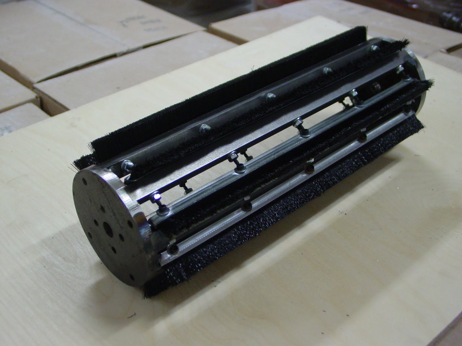
The REAL mover and shaker!


A close-up of the screen. Although this mesh count is considerably coarser than the powders being printed, this seems fine for general use. Any finer and the screen really starts to clog up.


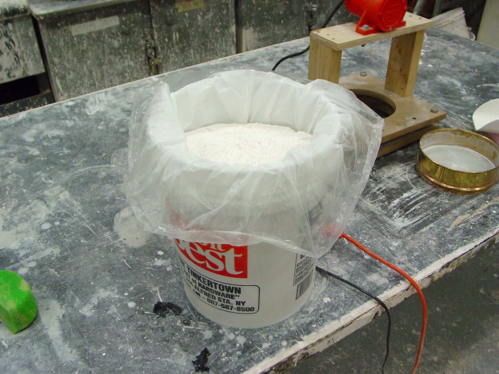
Setting things up: Place the machine over top of the bucket; place a plastic bag inside the bucket through the opening; press the screen into the opening, creating a seal between the plastic and the opening.


Progress during screening.


5 gallons of recycled powder, ready for printing!


This system worked surprisingly well for a prototype! It takes about a half hour to fill a 5 gallon bucket with material. If I were to build this again, I would re-design the location of the motor, as it does get in the way of access to the screen. Also, all that extra wood represents extra mass that the motor must move. It essentially robs the screen of that energy. Instead, I would locate the motor on the top horizontal wood piece, right next to the screen. This would probably require a second identical motor to balance the weight so that the screen could sit horizontally. I would also think about a hopper to allow for more automated use.

I've posted a video of this in action here...

Sunday, September 19, 2010

Designing a test tile

I’ve been printing some initial tests and will have images up soon.

In the meantime, I have designed a test tile using Rhino 3D. 3D printing is fairly new to me. As I get more experience, I’ll get a better idea of what is useful information and what is not. As of now, I’m testing for a few different aspects: namely linear shrinkage and resolution. Resolution will be affected by layer thickness and also by how much bleeding occurs during the printing process. For this second aspect, I have included both intrusions and protrusions from the main bar. With results that bleed too much, material within the holes will probably not depowder easily. Resolution of the protrusions will probably be a bit more forgiving in this respect. That’s what I’m thinking anyway. Well see how this translates in real life.


Side 1 - Intrusions and protrusions. The nominal values refer to the width of each feature. For the height / depth, I'm using three times half the width (i.e. the protrusion on the far right is 0.04" wide and 0.06" tall; the intrusions is 0.04" wide and 0.06" deep).


Side 2 - Id. No test is meaningful without it!


Side 3 - Intrusion test. A variation on side #1. The smaller dimensions on side #1 may be a bit too optimistic. These dimensions are more generous.


Side 4 - Shrinkage line. I'm using 100 mm, as this is common in ceramic shrinkage bar tests. 1 mm translates readily into 1%, making measurements straightforward.


Perspective showing overall dimensions - That's 0.39 x 4.57 inches. Also note the intrusion on the end. The sharp inside corners should be quite telling for depowdering/bleeding purposes.


Screen shot of the template file.


The Rhino file for this is found here…3DM file

I also have the STL output from this file here…STL file


Wednesday, September 8, 2010

Spray drying refinement

I haven’t forgotten about this blog. It’s actually been on my mind for some time. I’ve just been really busy. School has started and I’m overwhelmed at the moment. I’m looking forward to the near future when things settle down a bit and I can get back to focusing on this research.


I’ve been working on several fronts. With regards to testing powder behavior, I’ve built a system for measuring friction within the powder. This should allow me to predict how materials will behave in small batches before committing to larger amounts for the machine. I’ve also started using a new dry mixing system (it’s actually resurrected from the engineering department’s grave). I’ll document both of these as time permits. Finally, I’m still actively searching for a better way to screen material.

In the meantime, I did get some promising results. I re-ran some batches of ceramic powder through our spray drier equipment. In my original attempt, only 22.3% of the material I started off with in slip form ended up being usable after spray drying (where usable = passing through a 200 mesh screen). The vast majority was simply too large.

For this second batch, Hyojin suggested dropping the PEG down to 0.5% He also suggested making a volume suspension of 20%.

This worked out to be 52g dry / 80g water.

In batch terms…


This second batch sprayed much finer and the yield improved dramatically (isn’t it wonderful when theory translates into reality?). Decreasing the PEG and increasing the water increased the amount of material below 200 mesh from 22.3% up to 38.1%. There's probably a trade off somewhere I'm not aware of yet. For now I'm just glad things are working out. I'll be mixing this with binders in the next few days and will post the results soon!

Monday, August 16, 2010

Spray drying from scratch

Given my earlier conclusions regarding spray drying, I decided to further investigate this technique. I could continue to use a commercially prepared spray dried product, but where's the fun in that? Moreover, I want to have complete say over what the material I am using is made of. That is, after all, why I'm doing this.

I figured spray drying would be a fairly easy, straightforward process. Like many other things, the devil is in the details!

In researching more about this technique, I was surprised to learn of how many different industries use this process. Spray drying is used for everything from preparing dry food products like condensed milk, to pharmaceuticals and other chemical products. In ceramics, it is used to prepare material for dry pressing, as spray dried powders flow very nicely. This is crucial for consistent filling of dry pressing equipment. This ability to flow is also the reason why I think it makes sense for 3D printing.

The process is simple in theory. You pump a slurry (a material in suspension) through an atomizer (essentially a spray gun nozzle). The atomizer is aimed inside a sealed, heated chamber. As the slurry is sprayed into the warm environment, it forms little droplets. Thanks to surface tension, these airborne droplets take the shape of almost perfect spherical granules as they dry. As these granules fall, they are consolidated by the funnel-shaped bottom of the chamber into a jar below.

In theory it is simple. In practice, it is a fairly complex process. There is little control over the size and size distribution of the particles once the machine is up and running. These variables are actually a result of the suspension characteristics of the slurry being dried. So if the particles you get are too big... you need to start over with a different combination of materials. There's an art to spray drying; certainly more so than I first thought!

I met with Hiojin to devise a testing strategy. Much of his work deals with non-clay systems (i.e. alumina or other materials). As each recipe produces different results when spray dried, my first trial was simply a shot in the dark. There were a few things I gathered from our first meeting:

  • Spray drying is not a very efficient technique. I should expect to loose about half of the material I start with, so for whatever amount of powder I expect to yield, I should double what I start off with.
  • Dispersant: I will add a dispersant (in this case, Darvan 811) to help mix the suspension more thoroughly
  • Binder: This is required to give the granules strength after drying. I this case, I will use Polyethylene glycol (PEG). PEG comes in different molecular weights, with higher numbers resulting in longer chains. I'll use a medium weight (PEG 600) to start with
With respect to the size of the resulting granules...

If granules are too large... add water.
If granules are too small... add PEG

I started with a 30% volume suspension. This means 30 cc of ceramics for 70 cc of water.
To convert from volume to density for the ceramic materials… 30 cc * 2.6 g/cc (average density of powders) = 78 grams of ceramic powder needed.

So 78 grams of ceramic powder + 70 cc water = 30% volume suspension.

As for the amount of Darvan, I need to use about 0.2 mg/m2. In other words, I need 0.2 mg of Darvan to coat each square meter of material. I'll spare both you and I the calculations on this... needless to say, it is specific to the ceramic materials being used, as each material in the recipe has its own specific surface area.

Enough MATH! The final recipe looked like this:


The above amount filled a 5 gallon bucket when all the water was added.

The spray drier has two collection jars. The main jar collects the "usable" material. A secondary jar collects material which is super fine. I was hoping that this finer material might be usable. Even though it is theoretically granular, it is so fine that it no longer flows well. As is, it is unusable.

I screened the material from the main jar. After passing through a 200 mesh screen, the result was a super-compact, fine powder that doesn't clump.

Below are a few images I took of the process. Also, I just put up a short video here...


On the left, Matt and Sanjae preparing the spray drying equipment for a run. Watching them work together was a real treat: each seemed to know what the other was doing, almost telepathically. These guys are like the mercenaries of the spray drying world! On the right, the rightmost gauge indicates the temperature of the internal chamber. 115 C... ideal for our needs.


On the left, the ceramic slurry is constantly stirred during spray drying to avoid settling. Also visible is a peristaltic pump used to pump the slurry to the atomizer. On the right, the line from the pump feeds to the atomizer close to the bottom of the funnel. The atomizer inside the chamber actually points upwards, giving the slurry plenty of room to dry before falling back down. The yellow air-line supplies air to the atomizer (much like you would see in a regular spray gun for ceramic applications).


On the left, the main jar as it fills. On the right, the secondary jar collects the really fine material.


As might be expected, some of the atomized droplets land on the sides of the chamber before they have a chance to fully dry and drop. On the left, before and after images of the chamber, showing this accumulation of material over time. On the right, the access door to the chamber, and a closeup of the material buildup. This is remarkably similar to what one encounters as "overspray" when spraying ceramic glaze in a spray booth. Naturally as this texture builds up, it increases the surface area of the chamber walls, attracting more and more material and essentially diminishing the yield in the main collection jar. For this reason, the chamber needs to be cleaned periodically, even when running the same batch of material.


The fruit of all that labour: a very nice spreading, custom made powder.


After screening the results, here is what I have:


A yield of 22.3% is not that great. Oh well, at least there's room for improvement!

Overall, this has been a very rewarding experience for me. I have a much better understanding of what's involved in spray drying. The overall run took about 3 hours. Quite a bit of time and energy for such a small yield. On the other hand, this is the only way I can think of to make a free-flowing ceramic powder. And of course, if this works, there are always economies of scale.

I leave you with a few images of a large spray drier I visited at a clay production facility in Germany a few years back. It was too large too capture in one image. Needless to say, this would speed up my process just a bit  :-)


Tuesday, July 27, 2010

Designing a brush mill

Quite often, I make things that I only end up using a few times. The following is an example.

This post is chronologically out of place. It should have been posted before I considered spray drying. I'm not sure of its future viability in 3D printing, as the particle shape it creates dosen't seem conducive to spreading (see previous posts). Still, a fair bit of engineering and thought went into this project so I thoght it might be of future help. I present it here as food for thought. 

In order to fully mix the ceramic body, it was first wet mixed in slurry form and then completely dried. It was now in lump form. The question was how to get this stuff down to 200 mesh size. I used a combination of jaw crushing and plate milling, but that only got it down to about a 60 mesh. I could have tried sieving the material by hand but the yield would not have been very good (most of the material would not have passed 200 mesh; our plate mill creates -60 mesh material). In its dry state, clay is quite friable. All I really needed was a system that would physically rub the clay against the screen. This rubbing would break down the clay and get it past the screen.

Enter: Hyojin Lee

Hyojin works in the Engineering Department here at AU. He introduced me to a machine he had designed a while back. The machine was designed to mill alumina fibers. It used a rotating rotor with 8 metal rods which rubbed the fibers against a coarse screen (an 8 mesh screen). In doing so, it broke the fibers down, essentially acting as a mill. The beauty of this system was that it was gravity fed, so that there was always material in contact with the screen. Furthermore, the trough which supported the screen was spring-loaded and could travel independently of the rotor. The springs pulled the screen upwards, ensuring contact between it and the rotor blades. This was important so it could adjusted contact as things wore down.

The one issue with using it in my application was that my material and screen were much finer than what the machine was built for. The original rotors were much too coarse and wouldn't have made enough contact with my finer screen and materials. I needed something more pliant.

My solution was to replace the hard metal rotors of the original design with door brushes made of short nylon fiber (courtesy of MSC). These brushes gave me enough rigidity to force the clay against the screen, but enough flexibility that they could better account for irregularities in the geometry of the system. Their softness was also a good thing, given that a 200 mesh screen is fairly thin and wouldn't hold up to constant contact with metal rotor blades for very long.

The following images are a brief overview of the project.


The unmodified unit (left). On the right, the door brush material I bought came in 72" lengths. I cut it down and drilled the holes for it on my CNC mill (right). In fact, all parts were milled prior to assembly (CNCing is perfect for this type of work).


All critical parts were modeled in Rhino prior to starting, so I knew what lengths and what size holes to cut. Toolpaths for everything were created in RhinoCam. In order to ease alignment, I milled out recessed areas on the two end plates for the rotors. This allowed for a slip-fit (left). The image on the right shows all the components before assembly.


The rotors were welded in place. The brushes were then attached using hex bolts (in case I ever need to replace them).This thing weighs a ton... almost literally.


Detail of brushes and bolts (left). On the right, the original rotor, and its replacement, the newly designed brush-rotor.


The metal trough has an arc-shaped bottom which is slightly larger than the diameter of the rotor assembly (top left). This ensures good contact between the rotor blades and the screen. In the top right image, a closeup of the screen layers. The finer screen is the 200 mesh count. I decided to back this up with an 8 mesh screen for extra support. Both screens are stainless. The bottom image shows the trough fully assembled. Note the dangling springs. These pull the unit upwards towards the rotor during use.


On the left, a view of the rotor after its been loaded with material. On the right... -200 mesh material collecting below the machine after running it for several minutes.


Here is a video of the whole process in action... http://www.youtube.com/watch?v=3qqzw2xjciM